A terminal block wiring diagram is a visual representation that shows how electrical connections are made using terminal blocks. Terminal blocks are modular, insulated blocks used to secure and connect electrical wires or cables. These diagrams are commonly used in industrial control systems, automation, and electrical panel wiring to plan and document complex wiring connections. Here are some key aspects of a terminal block wiring diagram:
.jpg)
-
Identification: Terminal blocks are labeled with unique identifiers to indicate the connections they represent. These labels are typically alphanumeric or numeric to distinguish each terminal block and facilitate troubleshooting.
-
Wiring Connections: The diagram illustrates how wires from various components or devices are connected to terminals on the terminal block. Each wire is represented by a line on the diagram, and the connections are indicated by lines crossing or joining at the terminals.
-
Terminal Block Layout: The physical arrangement of terminal blocks and the organization of terminals within a block are shown in the diagram. This layout helps electricians and technicians understand how different components are interconnected.
-
Color Coding: In some cases, wiring diagrams may use color coding to differentiate between wires of different functions or voltages. For example, red wires might represent power connections, while blue wires could be used for control signals.
-
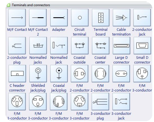
Schematic Symbols: Terminal block wiring diagrams often include schematic symbols to represent various electrical components, such as relays, switches, sensors, or motors. These symbols help convey the type and function of each component in the system.
-
Wire Labels: To further aid in clarity, wire labels or markers may be used in the diagram to indicate the purpose or destination of each wire. These labels help ensure that the wiring connections are made correctly during installation and maintenance.
-
Safety Considerations: Wiring diagrams may also include safety information, such as grounding points, fuse locations, or disconnect switches, to ensure compliance with safety standards and regulations.
Creating and understanding terminal block wiring diagrams is crucial for accurate installation, maintenance, and troubleshooting of electrical systems. These diagrams provide a visual representation of the wiring connections, allowing technicians to follow proper wiring practices and ensure reliable operation of electrical equipment and control systems.
.jpg)
How to Read Terminal Block Wiring Diagram
Reading a terminal block wiring diagram is essential for understanding how electrical connections are made using terminal blocks in industrial control systems, automation, and electrical panel wiring. Here are steps to help you read and interpret a terminal block wiring diagram effectively:
-
Identify the Terminal Blocks:
- Locate the terminal blocks within the diagram. Each terminal block is typically represented by a rectangular block with labeled terminals inside.
-
Understand Terminal Labels:
- Read and understand the terminal labels. Terminals are usually numbered or labeled with alphanumeric characters to identify specific connection points.
-
Follow the Wiring Connections:
- Trace the wiring connections from one component to another. Lines connecting terminals in the diagram represent electrical connections between devices or components.
-
Note Wire Paths:
- Identify the paths of wires between components. Different wire paths show how signals or power flow within the system.
-
Pay Attention to Colors and Symbols:
- Note any color codes or symbols used in the diagram. Colors and symbols can indicate specific wire functions or types of components.
-
Review Component Symbols:
- Look for symbols representing different components like sensors, motors, relays, switches, etc. These symbols help identify the type of component connected to a terminal block.
-
Understand the Circuit Logic:
- Analyze the wiring diagram to understand the logic of the circuit. Identify control signals, power supplies, signal paths, and any interlocks present in the system.
-
Check for Safety Features:
- Look for safety-related components such as grounding points, fuses, emergency stops, or disconnect switches. Ensure that safety features are correctly represented and interconnected in the diagram.
-
Refer to Documentation:
- Consult any accompanying documentation, manuals, or legends that provide additional information about the terminal block wiring diagram.
-
Verify Connections:
- Double-check the connections between components and ensure that they match the wiring diagram. Incorrect connections can lead to malfunctions or safety hazards.
- Seek Assistance if Needed:
- If you encounter complex or unclear aspects in the wiring diagram, seek assistance from experienced personnel or consult with electrical engineers for clarification.
Reading and interpreting terminal block wiring diagrams accurately is crucial for proper installation, maintenance, and troubleshooting of electrical systems. By following these steps and paying attention to details, you can effectively understand and work with terminal block wiring diagrams in various industrial and electrical applications.
Terminal Block Wiring Diagram You Can Refer To
I don't have the ability to display images or provide external links directly. However, I can describe a simple example of a terminal block wiring diagram to help you understand how they are typically structured:
Terminal Block Wiring Diagram Example:
-
Components:
- Terminal Blocks: Represented as rectangular blocks with labeled terminals inside.
- Wires: Lines connecting terminals to show electrical connections.
- Components: Symbols for different electrical components like switches, relays, and motors.
-
Layout:
-
Terminal Block 1 (TB1):
- Terminals: L1, L2, L3 (Power Inputs)
- Connection: L1 connects to Terminal 1 of Relay 1
- Connection: L2 connects to Terminal 2 of Relay 1
- Connection: L3 connects to Terminal 1 of Motor 1
-
Terminal Block 2 (TB2):
- Terminals: 11, 12, 13 (Control Inputs)
- Connection: Terminal 12 of TB2 connects to Terminal 3 of Relay 1
- Connection: Terminal 11 of TB2 connects to Terminal 2 of Motor 1
-
Relay 1:
- Contacts: NO1, COM1, NC1
- Connection: NO1 connects to Terminal 3 of Motor 1
-
Motor 1:
- Terminals: T1, T2, T3
- Power Connection: T1 connects to Terminal 3 of Relay 1
- Control Connection: T2 connects to Terminal 11 of TB2
-
-
Wire Paths:
- Solid lines connecting terminals indicate active electrical connections.
- Dashed lines may represent inactive connections or alternative paths.
-
Safety Features:
- Grounding points may be labeled with the symbol for ground (⏚).
- Fuse symbols could indicate overcurrent protection devices in the circuit.
This basic example illustrates how terminals, components, and connections are typically arranged in a terminal block wiring diagram. Such diagrams become more complex in real-world applications with multiple components, control signals, power supplies, and safety features.
For specific diagrams related to your project or application, you may refer to equipment manuals, technical documentation, or online resources from manufacturers or engineering resources for detailed terminal block wiring diagrams specific to your needs.